
a choice, generally meant as a jewel.
This procedure permits the creator to find the obligation regarding performing an activity or settling on a choice effectively, demonstrating the obligation of every hierarchical unit for distinctive parts of a solitary methodology.
Flowcharts portray certain parts of methodologies and they are typically supplemented by different sorts of graph. Likewise, in UML, a standard idea displaying documentation utilized within programming advancement, the action outline, which is a sort of flowchart, is only one of numerous diverse chart sorts.
Normal option names include: flowchart, process flowchart, utilitarian flowchart, methodology guide, procedure graph, useful procedure outline, business procedure model, procedure model, methodology stream chart, work process chart, business stream chart. The expressions "flowchart" and "stream diagram" are utilized reciprocally.

A 1944 graduate of Mogensen's class, Art Spinanger, took the instruments over to Procter and Gamble where he created their Deliberate Methods Change Program. An alternate 1944 graduate, Ben S. Graham, Director of Formcraft Engineering at Standard Register Industrial, adjusted the stream procedure outline to data handling with his improvement of the multi-stream methodology graph to show various archives and their relationships.[3] In 1947, ASME received an image set determined from Gilbreth's unique fill in as the "ASME Standard: Operation and Flow Process Charts."[4]
Douglas Hartree clarifies that Herman Goldstine and John von Neumann created a flowchart (initially, chart) to arrange machine programs.[5] His contemporary record is supported by IBM engineers[6] and by Goldstine's close to home recollections.[7] The first programming flowcharts of Goldstine and von Neumann can be seen in their unpublished report, "Arranging and coding of issues for an electronic processing instrument, Part II, Volume 1" (1947), which is repeated in von Neumann's gathered works.[8] Besides depicting the intelligent stream of control, flowcharts permitted software engineers to lay out machine dialect programs in machine memory before the advancement of low level computing constructs and assemblers.[9]
Flowcharts used to be a prevalent means for portraying machine calculations regardless are utilized for this purpose.[10] Modern methods, for example, UML movement outlines and Drakon-graphs can be thought to be expansions of the flowchart. In the 1970s the notoriety of flowcharts as an own technique diminished when intelligent work stations and third-era programming dialects turned into the basic devices of the exchange, since calculations can be communicated significantly all the more compactly as source code in such a dialect, furthermore on the grounds that outlining calculations utilizing flowcharts was more prone to bring about spaghetti code as a result of the requirement for gotos to portray discretionary hops in control stream. Regularly pseudo-code is utilized, which utilizes the basic phrases of such dialects without strictly sticking to the points of interest of a specific on
The initially organized strategy for recording methodology stream, the "stream procedure diagram", was acquainted by Frank Gilbreth with parts of the American Society of Mechanical Engineers (ASME) in 1921 in the presentation "Procedure Charts—First Steps in Finding the One Best Way".[2] Gilbreth's apparatuses rapidly discovered their route into mechanical designing curricula. In the early 1930s, a modern architect, Allan H. Mogensen started preparing agents in the utilization of a portion of the apparatuses of modern designing at his Work Simplification Conferences in Lake Placid, New York.
A 1944 graduate of Mogensen's class, Art Spinanger, took the instruments over to Procter and Gamble where he created their Deliberate Methods Change Program. An alternate 1944 graduate, Ben S. Graham, Director of Formcraft Engineering at Standard Register Industrial, adjusted the stream procedure outline to data handling with his improvement of the multi-stream methodology graph to show various archives and their relationships.[3] In 1947, ASME received an image set determined from Gilbreth's unique fill in as the "ASME Standard: Operation and Flow Process Charts."[4]
Douglas Hartree clarifies that Herman Goldstine and John von Neumann created a flowchart (initially, chart) to arrange machine programs.[5] His contemporary record is supported by IBM engineers[6] and by Goldstine's close to home recollections.[7] The first programming flowcharts of Goldstine and von Neumann can be seen in their unpublished report, "Arranging and coding of issues for an electronic processing instrument, Part II, Volume 1" (1947), which is repeated in von Neumann's gathered works.[8] Besides depicting the intelligent stream of control, flowcharts permitted software engineers to lay out machine dialect programs in machine memory before the advancement of low level computing constructs and assemblers.[9]
Flowcharts used to be a prevalent means for portraying machine calculations regardless are utilized for this purpose.[10] Modern methods, for example, UML movement outlines and Drakon-graphs can be thought to be expansions of the flowchart. In the 1970s the notoriety of flowcharts as an own technique diminished when intelligent work stations and third-era programming dialects turned into the basic devices of the exchange, since calculations can be communicated significantly all the more compactly as source code in such a dialect, furthermore on the grounds that outlining calculations utilizing flowcharts was more prone to bring about spaghetti code as a result of the requirement for gotos to portray discretionary hops in control stream. Regularly pseudo-code is utilized, which utilizes the basic phrases of such dialects without strictly sticking to the points of interest of a specific on
Programming
Charting
Primary article: Diagramming programming § Flowchart
Any drawing system can be utilized to make flowchart outlines, yet these will have no underlying information model to impart information to databases or different projects, for example, venture administration frameworks or spreadsheet. A few apparatuses offer extraordinary backing for flowchart drawing. Numerous programming bundles exist that can make flowcharts naturally, either straightforwardly from a programming dialect source code, or from a flowchart portrayal dialect. On-line online forms of such projects are accessible.
Programming
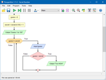
Flowgorithm
There are a few applications that utilize flowcharts to speak to and execute programs. By and large these are utilized as showing devices for apprentice understudies.
These include:
Flowgorithm
Raptor
LARP
Visual Logi
No comments:
Post a Comment